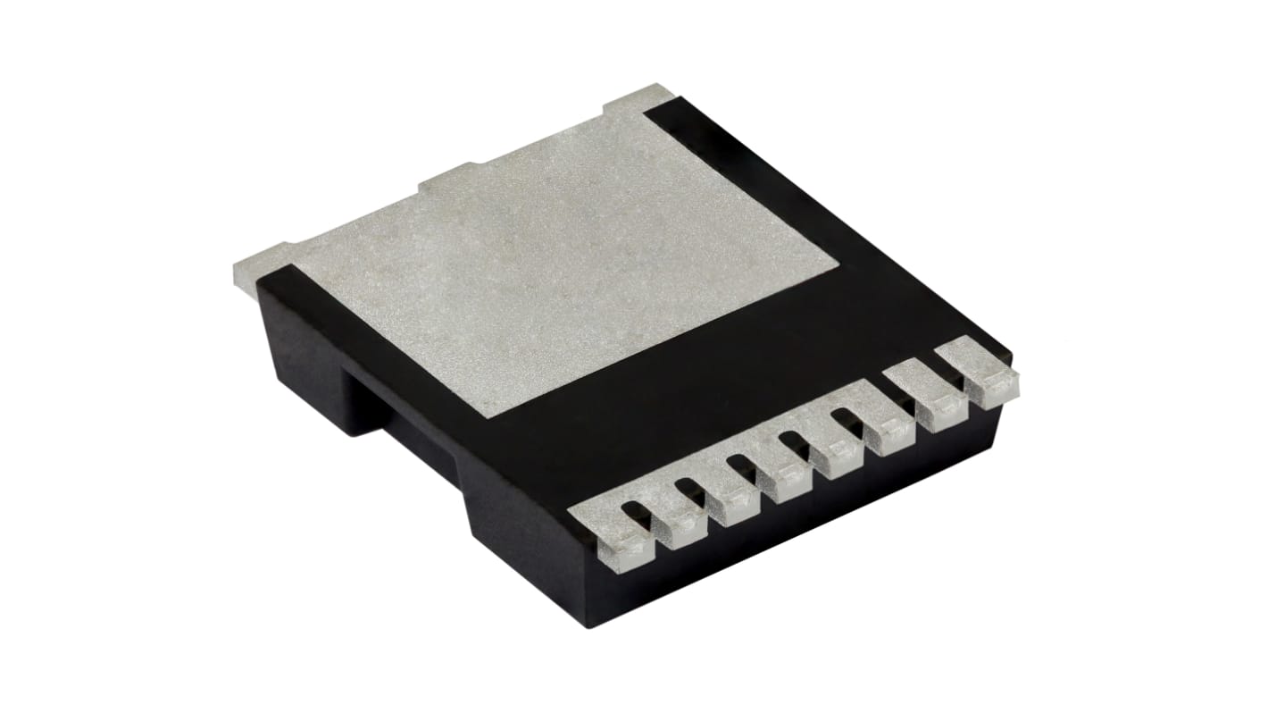
Vishay SIHK Type N-Channel MOSFET, 21 A, 650 V Enhancement, 8-Pin PowerPAK 10 x 12 SIHK125N60EF-T1GE3
- N° de stock RS:
- 268-8313
- Référence fabricant:
- SIHK125N60EF-T1GE3
- Fabricant:
- Vishay

Offre groupée disponible
Consulter les options de prix de grosSous-total (1 paquet de 2 unités)*
11,04 €
(TVA exclue)
13,36 €
(TVA incluse)
Frais de livraison offerts pour toute commande de plus de 90,00 €
En stock
- Plus 1 996 unité(s) expédiée(s) à partir du 20 juillet 2026
Besoin de plus? Cliquez sur " Vérifier les dates de livraison " pour plus de détails
Unité | Prix par unité | le paquet* |
|---|---|---|
| 2 - 48 | 5,52 € | 11,04 € |
| 50 - 98 | 4,96 € | 9,92 € |
| 100 - 248 | 4,07 € | 8,14 € |
| 250 + | 3,99 € | 7,98 € |
*Prix donné à titre indicatif
- N° de stock RS:
- 268-8313
- Référence fabricant:
- SIHK125N60EF-T1GE3
- Fabricant:
- Vishay
Spécifications
Documentation technique
Législations et de normes
Détails du produit
Recherchez des produits similaires en sélectionnant un ou plusieurs attributs.
Sélectionner tout | Attribut | Valeur |
|---|---|---|
| Marque | Vishay | |
| Channel Type | Type N | |
| Product Type | MOSFET | |
| Maximum Continuous Drain Current Id | 21A | |
| Maximum Drain Source Voltage Vds | 650V | |
| Series | SIHK | |
| Package Type | PowerPAK 10 x 12 | |
| Mount Type | PCB | |
| Pin Count | 8 | |
| Maximum Drain Source Resistance Rds | 0.125Ω | |
| Channel Mode | Enhancement | |
| Minimum Operating Temperature | -55°C | |
| Maximum Power Dissipation Pd | 132W | |
| Forward Voltage Vf | 1.2V | |
| Typical Gate Charge Qg @ Vgs | 45nC | |
| Maximum Operating Temperature | 150°C | |
| Length | 9.9mm | |
| Standards/Approvals | RoHS | |
| Automotive Standard | No | |
| Sélectionner tout | ||
|---|---|---|
Marque Vishay | ||
Channel Type Type N | ||
Product Type MOSFET | ||
Maximum Continuous Drain Current Id 21A | ||
Maximum Drain Source Voltage Vds 650V | ||
Series SIHK | ||
Package Type PowerPAK 10 x 12 | ||
Mount Type PCB | ||
Pin Count 8 | ||
Maximum Drain Source Resistance Rds 0.125Ω | ||
Channel Mode Enhancement | ||
Minimum Operating Temperature -55°C | ||
Maximum Power Dissipation Pd 132W | ||
Forward Voltage Vf 1.2V | ||
Typical Gate Charge Qg @ Vgs 45nC | ||
Maximum Operating Temperature 150°C | ||
Length 9.9mm | ||
Standards/Approvals RoHS | ||
Automotive Standard No | ||
- Pays d'origine :
- CN
Vishay SIHK Series MOSFET, 650V Maximum Drain Source Voltage, 21A Maximum Continuous Drain Current - SIHK125N60EF-T1GE3
This MOSFET is a high-voltage N-channel switching transistor designed for power conversion and control on printed circuit boards. It suits demanding electrical and electronic systems where elevated drain-to-source voltage handling and substantial current capability are required. The device is supplied in a Compact PowerPAK 10x12 package for PCB mounting and is intended for applications that operate across a wide temperature range.
Features and Benefits:
• 650V drain-to-source rating enables high-voltage switching
• 21A continuous drain current supports heavy load duty
• 0.125Ω Rds(on) reduces conduction losses at operating current
• 45nC typical gate charge allows efficient gate-drive management
• 132W power dissipation permits substantial thermal loading
• 21A continuous drain current supports heavy load duty
• 0.125Ω Rds(on) reduces conduction losses at operating current
• 45nC typical gate charge allows efficient gate-drive management
• 132W power dissipation permits substantial thermal loading
Applications
• Suitable for industrial motor drive inverter stages
• Ideal for high-voltage power supplies in automation systems
• Used for switch-mode power conversion in electrical equipment
• Can be used for medium-power traction and conversion modules
• Ideal for high-voltage power supplies in automation systems
• Used for switch-mode power conversion in electrical equipment
• Can be used for medium-power traction and conversion modules
What voltage stress can it withstand in switching circuits?
It can handle up to 650V between drain and source, making it appropriate for high-voltage topologies.
How does gate-charge affect drive design?
A typical gate charge of 45nC informs gate-driver current and switching-loss calculations during transition events.
What thermal extremes can it operate within?
Operational limits span from -55°C at the low end to 150°C at the high end for junction temperatures.
How many pins and what mounting style does it use?
It is an 8-pin device intended for PCB mounting in a PowerPAK 10x12 footprint.
What is the maximum permissible gate voltage?
The gate may be driven up to 30V relative to source without exceeding its gate‑source rating.
Liens connexes
- Vishay SIHK Type N-Channel MOSFET 650 V Enhancement, 8-Pin PowerPAK 10 x 12 SIHK125N60EF-T1GE3
- Vishay SIHK Type N-Channel MOSFET 650 V Enhancement, 8-Pin PowerPAK 10 x 12 SIHK045N60EF-T1GE3
- Vishay SIHK Type N-Channel MOSFET 650 V Enhancement, 8-Pin PowerPAK 10 x 12 SIHK085N60EF-T1GE3
- Vishay SIHK Type N-Channel MOSFET 650 V Enhancement, 8-Pin PowerPAK 10 x 12 SIHK105N60EF-T1GE3
- Vishay SIHK Type N-Channel MOSFET 650 V Enhancement, 8-Pin PowerPAK 10 x 12 SIHK185N60EF-T1GE3
- Vishay SIHK Type N-Channel MOSFET 600 V Enhancement, 8-Pin PowerPAK 10 x 12 SIHK155N60EF-T1GE3
- Vishay SIHK Type N-Channel MOSFET 650 V Enhancement, 8-Pin PowerPAK 10 x 12 SIHK105N60E-T1-GE3
- Vishay EF Type N-Channel MOSFET 650 V Enhancement, 4-Pin PowerPAK 8 x 8 SIHH125N60EF-T1GE3